")


Manual

PP-19-01 RE
Manual (further Guide) 9-mm pistols- machine guns "Vityaz" and "Vityaz-SN" is intended to study their design and maintain in constant combat readiness.
The manual contains information about the device, operating principle, rules for the operation and maintenance of Vityaz and Vityaz-SN submachine guns and their components.
Before starting operation, you should carefully study this Manual and in the future adhere to the rules for handling submachine guns set out in it.. This will ensure their trouble-free operation throughout the entire period of operation..
2
PP-19-01 RE
1 DESCRIPTION AND OPERATION OF THE VITYAZ AND VITYAZ-SN SUB-GUNS
1.1 Purpose of submachine guns
1.1.1 9-mm submachine guns "Vityaz" and "Vityaz-SN" are
powerful individual weapons and are designed to destroy live targets and unarmored vehicles.
1.1.2 Full name of submachine guns:
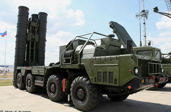
– 9-mm submachine gun PP-19-01, execution 10 Vityaz PP-19- 01.Sat-10. The appearance of the submachine gun in accordance with Figure A.1.
– 9-mm submachine gun PP-19-01, execution 20 Vityaz-SN PP-19- 01.Sat-20. The appearance of the submachine gun in accordance with Figure A.2.
– 9-mm submachine gun PP-19-01, execution 20 Vityaz-SN PP-19- 01.Sat-20-01. The appearance of the submachine gun in accordance with Figure A.3.
1.1.3 For firing from submachine guns, 9-mm pistol cartridges 9x19 PRS are used.
The design of submachine guns provides for the possibility of using 9-mm pistol cartridges with a bullet of increased penetration for firing. (9x19) index 7Н21. When using 7N21 cartridges for firing, remember, that the range settings on the sights of submachine guns correspond to the 9x19 PRS cartridge. therefore, if the submachine gun is brought to normal combat with 9x19 PRS cartridges, due to the higher initial speed of the bullet for the 7N21 cartridge, the point of impact will be higher, than when firing cartridges 9x19 PRS.
In the absence of cartridges 9x19 PRS and 7N21 for firing pistols- machine guns can be used cartridges 9x19 "Parabellum" of domestic and foreign production.
1.1.4 Submachine guns are fired automatically or single shot. Automatic firing is carried out short (to 5 shots) and long (to 10 shots) queues or continuous queue.
Technical characteristics of submachine guns
1.2.1 The main technical characteristics of submachine guns are given in the table 1.
Table 1
Characteristic name Caliber, mm
Cartridge type, caliber x dl. liner
Weight with unloaded magazine, without belt, kg, no more
Length, mm, no more
– with folded butt
3
The name of the submachine gun "Vityaz" "Vityaz-SN"
9x19 9x19
PP-19-01 RE – with folded butt
Width, mm, no more
– with folded butt – with folded butt
Height with magazine, mm, no more Store capacity, PC. rounds Sighting range, m
Muzzle velocity (cartridge 9x19 PRS), m / s, at least rate of fire, rounds / min
1.3 Composition of submachine guns
450 475 687 698
90 90 65 67
| practical rate, rounds / min – with automatic firing – in single shot | to 120 to 40 | to 120 to 40 |
1.3.1 The set of the submachine gun PP-19-01, execution 10 "Vityaz" includes:
– 9-mm submachine gun PP-19-01, execution 10 Vityaz PP-19- 01.Sat-10 (with a store) – 1 PC.;
– store PP-19-01.Sb 26 – 3 PC.;
– buttermilk 6Ю5 – 1 PC.;
– accessory in a pencil case PP-19Yu.Sb1 - 1 PC.; – ramrod PP-19Yu. 2 – 1 PC.;
– adapter 6Yu20. 7 – 1 pc.
clip-acPrPep-e1zh9.nYuoeSubs2tr–oi4sshtvto PP-19Ю Сб3 – 2 PC.
– shopping bag and accessories PP-19-01Sh – 1 PC.;
– belt for wearing 6Sh5 - 1 PC.;
– form PP-19-01 FD – 1 PC.;
– operation manual PP-19-01.RE - 1 PC. on 12 products
1.3.2 The set of the submachine gun PP-19-01, execution 20 "Knight-
CH" includes:
– 9-mm submachine gun PP-19-01, execution 20 Vityaz-SN PP-19-
01.Sat-20 (PP-19-01.Sat-20-01) (with a store) – 1 PC.;
– store PP-19-01.Sb 26 – 3 PC.;
– buttermilk 6Ю5 – 1 PC.;
– accessory in a pencil case PP-19Yu.Sb1 - 1 PC.; – ramrod PP-19Yu. 2 – 1 PC.;
– adapter 6Yu20. 7 – 1 pc.
– clip PP-19.Yu Sb2 - 4 PC
– fastening device PP-19Yu.Sb3 - 2 PC.
– shopping bag and accessories PP-19-01Sh – 1 PC.;
4
PP-19-01 RE
– belt for wearing 6Sh5 - 1 PC.;
– form PP-19-01 FD – 1 PC.;
– operation manual PP-19-01.RE - 1 PC. on 12 products
1.4 The device and operation of submachine guns
1.4.1 The device of the submachine gun "Vityaz"
Submachine gun "Vityaz", in accordance with Figure A.4, comprises: barrel with receiver, stock and receiver cover; prison; return mechanism; receiver lining; muzzle brake; handguard; shop; Trigger.
1.4.2 The device of the submachine gun "Vityaz-SN"
Submachine gun "Vityaz-SN", in accordance with Figure A.5, comprises: barrel with receiver, stock and receiver cover; prison; return mechanism; receiver lining; muzzle brake; handguard; shop; Trigger.
Submachine gun "Vityaz-CH" can be supplied in two versions. In the PP-19-01.Sb-20 version, the submachine gun is equipped with a Picatinny rail for mounting collimator and optical sights, located on the cover of the receiver. In the version of PP-19- 01.Sb-20-01 submachine gun is equipped with a standard rail for mounting optical and collimator sights, located on the left side of the receiver.
1.4.3 The work of automatic submachine guns
The work of automation of submachine guns is based on the principle of using the recoil energy of a free shutter.
When fired, powder gases press on the bottom of the sleeve. The shutter moves back together with the sleeve, but, since its mass is much greater than the mass of the bullet, the shift of the shutter by the time the bullet leaves the bore is insignificant and the destruction of the sleeve under the pressure of the powder gases does not occur. After the bullet leaves the bore, the shutter moves back by inertia.
When moving back, the ejector bolt removes the cartridge case from the chamber and, using a reflector, ejects it from the receiver. At the same time, the bolt compresses the return mechanism spring and cocks the hammer.. The trigger stands on the self-timer sear and is held in the cocked position..
The shutter returns to the forward position under the action of the return mechanism., at the same time, he sends a cartridge from the magazine to the chamber and closes the bore. At the end of the movement to the forward position, the shutter turns the self-timer and removes the self-timer sear from under the cocking of the trigger..
5
PP-19-01 RE
If the translator is set to automatic fire, then the shooting will continue until then, while the trigger is pulled and there are cartridges in the magazine.
If the translator is set to single fire, then the trigger, after being released from the self-timer sear, will cock the single-shot sear. To fire the next shot, you need to release the trigger and press it again.
1.5 The device and operation of the components and mechanisms of pistols- guns
The arrangement of parts and mechanisms of the Vityaz and Vityaz-SN submachine guns is in many ways similar, therefore, when describing the device of a pistol- machine gun "Vityaz-SN" parts and mechanisms, having the same design with the Vityaz submachine gun are not considered separately.
The description of the operation of the mechanisms is the same for the Vityaz and Vityaz-SN submachine guns.
1.5.1 The device of parts and mechanisms of the Vityaz submachine gun 1.5.1.1 Barrel with receiver
Barrel with receiver, stock and receiver cover
is the main supporting structure of the submachine gun and, in accordance with Figure A.6, comprises: butt; receiver; receiver cover; retainer base; forearm rings with check; fly pads; trunk; neck; arm.
The receiver consists of a casing with left and right angles, liner, butt plate and jumper. The receiver has: inside - a reflective protrusion to reflect the sleeves, located on the left corner; top - bends and guides for guiding the shutter; below - a window for the neck and a window for the trigger; on the side walls - holes for the axes of the firing mechanism and translator; on the right wall - two fixing recesses for setting the translator to the automatic firing mode (AB) and single shooting (FROM). On the left side of the receiver there is a riveted bar for mounting optical and collimator sights. A safety bracket is riveted to the bottom of the receiver.
The neck is made of high-strength plastic. The neck is inserted into the insert with the front hook and fixed with the axle, passing through the hole in the safety bracket. A magazine latch with a latch spring is installed in the neck on the axis. A plastic handle is attached to the receiver with a screw.
6
PP-19-01 RE
The barrel is pressed into the receiver liner and fixed with a pin. The base of the latch and the front sight block are pressed onto the barrel. In the block of the front sight, the base of the front sight with the front sight is installed. On the front end of the front sight on the left side there is a swivel for attaching the front end of the belt, and bottom – seat for attaching a flashlight or target designator. On the barrel between the base of the latch and the front sight block there is a forearm ring with a check, designed for attaching the forearm. On the trunk there is a transverse hole for checks. A muzzle brake is screwed onto the muzzle of the barrel, which is fixed by a spring-loaded latch located in the front sight block.
Butt is attached to the butt plate of the receiver. Example, in accordance with Figure A.7, comprises: the back of the butt; top link; ferrule with ferrule; lower link, interconnected by welding. In the clip of the butt there is a swivel for attaching a belt. The butt is attached to the butt plate of the receiver using the butt axis. In the butt plate of the receiver there is a butt lock with a spring, locking stock in reclined position. In the folded position, the stock is fixed with a latch, located in front of the receiver on the left.
The receiver cover is attached to the base of the latch with the help of an axis. in the channel, located in the upper part of the latch base is a latch with a spring. When disassembling the submachine gun, the latch holds the receiver cover in the tilted position. When the cover is closed, the front end of the latch comes out of the channel and locks the handguard.
1.5.1.2 prison
The shutter serves to send the cartridge into the chamber, closure of the bore, breaking the primer and extracting the cartridge case. prison, in accordance with Figure A.8, comprises: prison grounds; ejector axle; ejector; ejector springs; striker springs; bushings; striker pin; drummer. shutter has: on the front end there is a cylindrical cup for placing the bottom of the sleeve and a groove for the ejector; inside - a channel for a return mechanism and a stepped channel for a drummer with a bushing and a drummer spring; on the sides - grooves for movement along the guides of the receiver, sloping surface to ensure reflection of the liner, reload handle, holes for the ejector axle and striker pin. There is a tab on the right side of the shutter to interact with the self-timer lever.
7
PP-19-01 RE
An ejector with a spring is installed in the shutter on the axis. The ejector has a hook for gripping the sleeve and a hole for the ejector axis.
A striker is placed in the stepped channel of the shutter, bushing and striker spring. The striker pin secures the striker. The drummer has a striker and a ledge for the drummer pin, and at the rear end there are protrusions for supporting the drummer bushing.
1.5.1.3 barrel pad
The barrel pad serves to protect the shooter's hands from touching the bolt and barrel. barrel pad, in accordance with Figure A.9, comprises: rear ring; overlays; front ring; tube. The cover is made of wood. It is fixed on the tube by means of front and rear rings.. The barrel pad with the front end of the tube is put on the nozzle of the front sight block. The rear ring of the handguard enters the groove on the base of the latch and when closing the cover of the receiver, the receiver is fixed from moving by the front end of the latch.
1.5.1.4 Return mechanism
The return mechanism is designed to return the shutter to the forward position.. is he, in accordance with Figure A.10, comprises: return spring guide; return spring; rod; coupling. A limiter is installed on the return spring guide, in which the shutter strikes when it comes to the rear position.
1.5.1.5 The trigger mechanism
The trigger mechanism is used to release the trigger from the combat platoon or from the self-timer platoon, hitting the striker, ensuring automatic or single firing, ceasefire, to prevent shots when the shutter does not reach the forward position and to put the submachine gun on the safety.
The trigger mechanism is installed in the receiver, fastened with axes, and, in accordance with Figure A.11, comprises: trigger; axes; self-timer springs; chicken; self-timer; mainspring; translation.
The trigger mechanism includes a trigger, whispered single shot, sear springs, trigger stop and bushing.
The trigger is used to keep the trigger cocked and pull the trigger. It has a curly protrusion, axle hole, rectangular ledges and "tail".
The single-shot sear is designed to hold the trigger after a shot in the rearmost position when firing a single shot.. It is on the same axis with the trigger. The sear has a socket for a spring, axle hole and stepped lug, which the
overlapped by the interpreter's sector during automatic firing and 8
PP-19-01 RE
stops whispering. Besides, a stepped protrusion limits the rotation of the translator sector when setting the safety lock.
The trigger limiter limits the rotation of the trigger when it comes to its rearmost position.
The trigger with a mainspring is used to strike the drummer. There is a combat platoon on the trigger, self-timer platoon, pins and axle hole. The mainspring is put on the trigger trunnions and acts on the trigger with its loop, and the ends on the rectangular ledges of the trigger.
The self-timer is used to automatically release the trigger from the self-timer cocking during automatic firing., and also protects against a shot when the shutter does not reach the forward position. It has a protrusion to hold the trigger on the cocked self-timer and a lever to rotate the self-timer.
On the same axis with the self-timer is its spring. Its short end is connected to the self-timer., and its long end is located along the left wall of the receiver and enters the annular grooves on the axes of the self-timer, trigger and trigger, keeping the axes from falling out.
The translator is designed to install a submachine gun for automatic or single shooting, as well as the fuse. It has a sector with trunnions, which are placed in the holes in the walls of the receiver. The upper position of the translator corresponds to installing it on the fuse, medium - for automatic shooting ('AB') and lower - for single shooting («From»).
1.5.1.6 receiver cover
The cover is designed to protect the shooter from contact with the bolt and protect the mechanisms of the submachine gun from contamination.. She is, in accordance with Figure A.12, consists of a lid, sight bodies, steel, rear sight springs and rear sight axles. The cover is a U-shaped stamped part. At the rear end of the cover there is a cutout for the protrusion of the return spring guide. On the right side, the cover has a stepped cutout for the ejection sleeves to go out and for the passage of the bolt handle.. The body of the sight is riveted on top of the cover. A rear sight is mounted on the axis in the body of the sight. The rear sight can be rotated on the axis and occupy two positions. On the rear sight are the numbers "1" and "2", which corresponds to the firing range settings 100 and 200 m. The rear sight is fixed in working positions by a leaf spring, located in the body of the sight. There are two protrusions in front of the body of the sight., limiting the rotation of the lid when opening.
1.5.1.7 handguard 9
PP-19-01 RE
The forearm serves to make it easier to hold the submachine gun and protect the shooter's hands from burns.. It, in accordance with Figure A.13, consists of forearm and leaf spring. The forearm is made of wood. The forearm is attached to the barrel by a forearm ring. The back of the forearm is inserted into the receiver. There are notches and notches in the back of the forearm, in which the leaf spring is placed. The spring serves to exclude the pitching of the forearm.
1.5.1.8 Score
The magazine is designed to place cartridges and feed them into the receiver.. The main parts of the store are made of high-strength plastic. Score, in accordance with Figure A.14, comprises: magazine covers; store cases; feeder; springs; striker plate.
The magazine body connects all parts of the magazine. The shop building has: on the side walls at the top - bends for holding and guiding cartridges and longitudinal grooves for attaching an adapter when equipping a magazine from clips; on the side walls at the bottom - protrusions for attaching the magazine cover; on the front wall inside - a ledge to limit the rise of the feeder; on the back wall – support ledge for attaching to the receiver and three holes for controlling the number of cartridges in the magazine. The top hole matches 10 patron, average – 20 patron, lower - 30 patron. On the right side of the case, the marking of the used cartridge "9x19" is applied..
From below, the store case is closed with a store cover. The cover has a hole for the protrusion of the striker plate.
Feeder is placed inside the case, spring and striker plate. The spring with its extreme coil is attached to the striker plate.
1.5.2 The device of parts and mechanisms of the Vityaz-SN submachine gun 1.5.2.1 Barrel with receiver
Barrel with receiver, stock and receiver cover
is the main supporting structure of the submachine gun and, in accordance with Figure A.15, comprises: butt; receiver; receiver cover; aiming block; forearm rings with check; fly pads; trunk; neck; arm.
The receiver consists of a casing with left and right angles, liner, butt plate and jumper. The receiver has: inside - a reflective protrusion to reflect the sleeves, located on the left corner; top - bends and guides for guiding the shutter; below - a window for the neck and a window for the trigger;
on the side walls - holes for the axes of the firing mechanism and 10
PP-19-01 RE
translation; on the right wall - two fixing recesses for setting the translator to the automatic firing mode (AB) and single shooting (FROM). In the version PP-19-01.Sb-20-01, a bar for mounting optical and collimator sights is riveted on the left wall of the receiver. A safety bracket is riveted to the bottom of the receiver.
The neck is made of high-strength plastic. The neck is inserted into the insert with the front hook and fixed with the axle, passing through the hole in the safety bracket. A magazine latch with a latch spring is installed in the neck on the axis. A plastic handle is attached to the receiver with a screw.
The barrel is pressed into the receiver liner and fixed with a pin. An aiming block and a front sight block are pressed onto the barrel. In the block of the front sight, the base of the front sight with the front sight is installed. From below on the front sight there is a seat for attaching a flashlight or target designator. On the barrel between the sighting block and the front sight block there is a forearm ring with a pin designed for attaching the forearm. On the trunk there is a transverse hole for checks. There is a swivel on the forearm ring for attaching the front end of the belt. A muzzle brake is screwed onto the muzzle of the barrel, which is fixed by a spring-loaded latch located in the front sight block.
Butt is attached to the butt plate of the receiver. Example, in accordance with Figure A.16, comprises: the back of the butt; top link; ferrule with ferrule; lower link. In the clip of the butt there is a swivel for attaching a belt. On the top link of the butt there is a hook for fixing the butt in the folded position.
The butt is attached to the butt plate of the receiver using the butt axis. In the butt plate of the receiver there is a butt lock with a spring, locking stock in reclined position. In the folded position, the butt is fixed with a hook, located on the upper thrust of the butt, behind the annular groove on the protruding part of the barrel pin.
The receiver cover is attached to the aiming block with the help of an axis. A spring located on the axles, which, when disassembled, holds the cover in the open position. A sighting bar with a spring is installed in the aiming block. On the bar there are divisions with the numbers "5", «10», «15». «20», which corresponds to the firing range settings 50, 100, 150 and 200 m.
2.2 barrel pad
The handguard serves to protect the shooter's hands from touching the
breech and trunk. barrel pad, in accordance with Figure A.17, includes
of: rear ring; overlays; front ring; tube. Overlay made 11
PP-19-01 RE
plastic. It is fixed on the tube by means of front and rear rings.. The barrel pad with the front end of the tube is put on the nozzle of the front sight block. The rear ring of the handguard enters the groove on the aiming block and is fixed by the rotary pin of the handguard.
1.5.2.3 receiver cover
The cover is designed to protect the shooter from contact with the bolt and protect the mechanisms of the submachine gun from contamination.. She is, in accordance with Figure A.18, consists of cover and strap. The cover is a U-shaped stamped part. At the rear end of the cover there is a cutout for the protrusion of the return spring guide. On the right side, the cover has a stepped cutout for the ejection sleeves to go out and for the passage of the bolt handle.. On top of the cover there is a Picatinny type rail for mounting optical and collimator sights.. In the front of the bar there is a slot for placing the spring and a hole for the axle..
In the version of PP-19-01.Sb-20-01, in accordance with Figure A.19, a hinge is riveted to the lid instead of a strap, with which the receiver cover is attached to the aiming block.
1.5.2.4 handguard
The forearm serves to make it easier to hold the submachine gun and protect the shooter's hands from burns.. The forearm is made of high-strength plastic. On the outer surface of the forearm, there are protrusions and ribs for ease of holding by hand.. The forearm is attached to the barrel by a forearm ring.. At the back of the forearm, in accordance with Figure A.20, there is a ledge -A, which the forearm is inserted into the receiver.
1.5.2.5 prison, return mechanism, trigger mechanism, score
Shutter device, return mechanism, trigger mechanism and magazine similar to the arrangement of these mechanisms in a pistol- machine gun "Vityaz".
The position of the parts and mechanisms of the submachine gun before loading
The shutter under the action of the return mechanism is in the extreme
forward position. The return spring has the least preload. The self-timer lever is turned forward by the action of the self-timer tab and
down. 12
PP-19-01 RE
The trigger is pulled down and rests on the shutter. Drummer under the action of the trigger moved forward. The mainspring is at its lowest preload, with her noose she presses the trigger to the bolt, and with curved ends presses the rectangular protrusions of the trigger to the bottom of the receiver, while the “tail” of the trigger is in the forward position.
The translator is in the uppermost position and closes the stepped cutout in the receiver cover (the translator is on safety); the translator sector overlaps the stepped protrusion of the single-shot sear and is located above the right rectangular protrusion of the trigger (locks the trigger).
1.5.4 The operation of parts and mechanisms of the submachine gun during loading To load the submachine gun, you must attach an equipped magazine, put the translator on automatic or single fire (position «AV» or «OD»), pull the bolt by the handle back to the stop and release sharply. If there is no immediate opening of fire, then you need to put the submachine gun on the fuse.
Submachine gun loaded.
When setting the interpreter to automatic or single
shooting, a stepped cutout for the bolt handle in the receiver cover is released, the translator sector releases the rectangular ledge of the trigger and does not prevent it from turning.
When the bolt is pulled back, the barrel bore opens., return spring is compressed, the trigger under the action of the shutter rotates on the axis, mainspring is twisted, the cocking of the trigger jumps over the curly ledge of the trigger, and then the trigger is on the self-timer ledge, the self-timer lever is then rotated up and in the path of the shutter projection.
As soon as the bottom surface of the bolt passes the magazine, the feeder, under the action of the magazine spring, lifts the cartridges all the way into the bends of the magazine. When moving forward under the action of the return mechanism, the bolt pushes the upper cartridge out of the magazine, sends it into the chamber and closes the bore. When coming to the forward position, the ejector hook jumps into the annular groove of the sleeve, and the self-timer lever is rotated forward and down by the action of the shutter, removing the self-timer sear from under the self-timer cocking; the trigger under the action of the mainspring turns and becomes a combat platoon on the curly ledge of the trigger.
Cartridges in the store under the action of the feeder rise to the stop
upper cartridge in the bolt. 13
PP-19-01 RE
The translator put on the fuse closes the stepped cutout of the receiver cover and gets in the way of the movement of the bolt handle, preventing it from moving backwards; translator sector turns forward and becomes over the right rectangular ledge of the trigger (locks the trigger).
1.5.5 The work of parts and mechanisms of a submachine gun when firing
1.5.5.1 The work of parts and mechanisms of a submachine gun during automatic firing
To conduct automatic shooting, you must put the translator on automatic shooting "AB", if it was not delivered when loading, aim and pull the trigger.
When the interpreter is set to automatic firing, the interpreter sector releases the rectangular ledge of the trigger (unlocks the trigger), but overlaps the stepped protrusion of the single-shot sear. The trigger gets the ability to rotate around its axis, the single-shot sear is kept from turning by the interpreter sector.
When you press the tail of the trigger, its curly protrusion disengages from the cocking of the trigger. The trigger under the action of the mainspring rotates on its axis and vigorously strikes the drummer. The striker breaks the cartridge primer with a striker. The percussion composition of the primer ignites and ignites the powder charge through the seed holes in the bottom of the cartridge case.. It occurs shot.
The bullet under the action of powder gases moves forward along the bore, and the shutter, under the action of powder gases on the bottom of the sleeve, moves back together with the sleeve. After the bullet leaves the bore, the shutter moves back by inertia. When moving back, the bolt removes the cartridge case from the chamber and, using a reflector, ejects it from the receiver. At the same time, the bolt compresses the return mechanism and cocks the hammer.. The trigger stands on the self-timer sear and is held on it until the shutter arrives in the front position. The shutter reaches the rear position and moves forward under the action of the return mechanism.. When moving forward, the bolt sends the upper cartridge from the magazine into the chamber and closes the bore. At the end of the forward stroke, the shutter protrusion presses the self-timer lever and releases the self-timer sear from- under platoon is afraid of self-timer. The trigger under the action of the mainspring turns and strikes the drummer. It occurs shot. The work of parts and mechanisms of the submachine gun is repeated. Automatic firing will continue until, while the trigger is pressed and
store has ammo. 14
PP-19-01 RE
Release the trigger to stop firing.. In this case, the trigger turns under the action of the mainspring and its curly protrusion gets in the way of the cocking of the trigger, the trigger becomes on a combat platoon. Shooting stops, but the submachine gun remains loaded, ready for further automatic firing.
1.5.5.2 The work of parts and mechanisms of a submachine gun during single firing
To fire a single shot, it is necessary to put the translator on single shooting "OD", aim and pull the trigger.
When the translator is placed in the position for single shooting, the translator sector releases the rectangular trigger protrusion (unlocks the trigger) and stepped ledge whispered single firing.
When you press the "tail" of the trigger, its curly protrusion disengages from the cocking of the trigger. The trigger under the action of the mainspring rotates on its axis and vigorously strikes the drummer. It occurs shot. After the first shot, parts and mechanisms do the same work., as with automatic shooting, but the next shot does not occur, since, together with the trigger, the single-shot sear rotates and its hook gets in the way of the movement of the cocking of the trigger. therefore, after the shutter rotates the self-timer and releases the trigger, the cocking of the trigger jumps behind the sear of single firing and the trigger stops in the rear position.
In order to fire the next shot, you need to release the trigger and pull it again. When the trigger is released, under the action of the mainspring, it rotates along with the single-shot sear, the single firing sear disengages from the cocking of the trigger and releases the trigger. The trigger under the action of the mainspring turns and stands on the curly ledge of the trigger. When the trigger is pressed, its curly protrusion disengages from the cocking of the trigger and the work of parts and mechanisms is repeated. Another shot is fired.
1.5.6 The device of the component parts of the submachine gun
1.5.6.1 Carrying strap
The carrying strap is used to carry the submachine gun in
combat and marching position. Carrying strap, in accordance with
Figure A.21, comprises: belt tape; prunes; buckle; carbine. On one 15
PP-19-01 RE
a carabiner is fixed at the end of the belt tape with a metal lining and a ring; the other end of the ribbon is made in the form of a loop with a metal buckle and a loop. Due to the loop and buckle, the length of the belt can be adjusted to suit the individual characteristics of the shooter.
1.5.6.2 Shopping bag and accessories
Magazine bag and accessories for storing and carrying magazines, ammo clips and accessories. She is, in accordance with Figure A.22, consists of two parts: shopping bags and accessory bags. Accessory bag attaches to magazine bag with straps, which are threaded through the holder, sewn to the front wall of the shopping bag, and fastened with fasteners. If necessary, the magazine bag and accessory bag can be used separately from each other. In the inside of the shopping bag, in accordance with Figure A.23a), there are three shops, as well as a ramrod and an adapter, for which there are separate pockets, located in partitions between compartments for shops. There are two clip pockets on the sides, in which two clips with cartridges are placed. On the outer wall of the clip pockets there are pockets for placing empty clips. Large mag bag compartment and clip pockets with flap closure, which are fastened with clasps. Two loops are sewn on the back wall of the shopping bag for putting the bag on the waist belt.. In the inside of the accessory bag, in accordance with Figure A.23b), there are two departments: large compartment accommodates two mounting devices, and in the small - butter dish. In the partition between the compartments there is a pocket for placing a pencil case with accessories. Bag for accessories closed with a flap, which is held in place by braces.
1.5.6.3 Belonging to a submachine gun
Accessory for dismantling, assembly, cleaning and lubricating the submachine gun, accelerated magazine loading ammo. Mounting device allows you to connect two magazines into one block to speed up the change of magazines during intense shooting.
To accessories, in accordance with Figure A.24, relate: clip; şompol; protyrka; planer; screwdriver; penalty, oiler; fastening device; adapter.
The ramrod is used for cleaning and lubricating the bore, as well as channels and cavities of the submachine gun. It has a head with a hole for
16
PP-19-01 RE
punch, guide part and end with a slot for rags or tow. At the end of the ramrod there is a thread for screwing the wipe.
Wiping is used to clean and lubricate the bore, channels and other cavities of the submachine gun. It has an internal thread for screwing onto a ramrod.. On the surface of the wipe there is a corrugation for wrapping rags or tow.
Screwdriver and punch are used when disassembling and assembling the gun- gun. The cutout at the end of the screwdriver is designed to screw in and unscrew the front sight.. For ease of use, the screwdriver is inserted into the side hole of the case.
The pencil case is designed to store wiping, screwdrivers and punches and closed with a lid. Pencil case can be used as a ramrod handle and screwdriver handle. To do this, it has an oval hole with flanges., into which the ramrod is inserted when cleaning the bore, and an oval hole for a screwdriver.
The oiler is designed to store lubricating oil.
The clip is used for carrying cartridges and accelerated equipment of the magazine with cartridges.. Fits in the cage 15 rounds. It has two longitudinal grooves and a leaf spring., to keep cartridges from falling out. Besides, leaf spring provides a strong connection of the cage with the adapter.
The adapter is used to connect the clip with the magazine when it is equipped with cartridges.. He has: from below (broadened part) - two folds, that fit into the corresponding grooves on the neck of the magazine; top - two longitudinal grooves for the holder, cage spring hole and stop, limiting the progress of the clip when it is inserted into the adapter.
The fastening device is used to connect magazines. It consists of right and left brackets, riveted. At the bottom of the bracket there are bends for placing the magazine cover, and in the upper part - a spring foot to hold the magazine in the mounting device.
1.6 Marking
On the submachine gun are applied:
– manufacturer's trademark;
– item number (the first two digits of the number indicate the year of manufacture) – cartridge type used.
On the store of the submachine gun are applied:
– manufacturer's trademark;
– cartridge type used.
17
PP-19-01 RE
1.7 Packaging
1.7.1 Submachine guns are delivered to the consumer in wooden boxes, dyed in protective color. Twelve submachine guns with all accessories are placed in each box and secured with special inserts.. Inside the box is lined with paraffin paper. Before capping, the bottom and walls of the box are additionally lined with inhibited paper.. The lid of the box is tightly fixed to the base with screws and sealed.
1.7.2 The box is labeled as follows::
– number of packed products;
– name of the inhibitor and date of conservation;
– manipulation signs "Fragile - be careful", "Top", "Keep away from
moisture".
PP-19-01 RE
2 USING THE SUB-GUN FOR THE INTENDED USE
2.1 General instructions
The submachine gun must be kept in perfect working order and ready for use.. This is achieved by timely cleaning and lubrication., careful attitude, proper storage, timely maintenance and troubleshooting.
2.2 Safety Instructions
2.2.1 Disassembly and assembly training is recommended to be carried out on training submachine guns. Training on combat submachine guns is allowed with special care in handling parts and mechanisms..
2.2.2 Before preparing the submachine gun for firing, and before cleaning and lubricating, make sure that, that the submachine gun is not loaded. During all training actions with a submachine gun, do not point it at people or to the side, where people might be.
2.2.3 Shooting in a closed shooting range should be carried out only if there is a supply and exhaust ventilation, since the powder gases emitted during firing are toxic. At the end of the shooting, unload the submachine gun and put it on the safety. After intense shooting, it is forbidden to touch the part of the barrel protruding beyond the forearm and the muzzle brake due to the risk of burns.. If you receive delays to eliminate them, you should be guided by the instructions in clause 3.5 of this Guide.
2.3 Preparing a submachine gun for firing
2.3.1 Preparation of a submachine gun for firing is carried out in order to ensure its trouble-free operation..
To prepare a submachine gun for firing, it is necessary to check the quality of cleaning, inspect the disassembled submachine gun and lubricate (if necessary) thin layer of lubricant, inspect the assembled submachine gun.
2.3.2 Immediately before shooting, wipe the bore of the barrel dry (rifled part and chamber), inspect the cartridges and equip the store with them. It is not allowed to use for shooting cartridges with traces of corrosion, with dents on the sleeve, with a bullet oscillating or pressed into the cartridge case.
2.3.3. To equip the magazine with cartridges, you need:
take one hand shop, and in the other hand, cartridges with bullets to the little finger so, 19
PP-19-01 RE
so that the bottom of the sleeve rises slightly above the thumb and forefinger;
– by pressing the thumb, insert the cartridges one by one under the bends of the side walls with the bottom of the sleeve to the rear wall of the magazine;
– after equipping the magazine, put it in the compartment of the magazine bag or attach it to the submachine gun.
2.3.4 To equip the magazine with cartridges from the clip, you need, in accordance with Figure A.25:
– attach the adapter to the store like this, so that its bends fit into the corresponding grooves on the magazine body;
– holding magazine with one hand, with the other hand, insert the clip with cartridges into the adapter, in this case, the cartridges should be directed by bullets towards the front wall of the magazine;
– pressing on the case of the sleeve (at the bottom) top chuck, sink the ammo into the magazine;
– remove the empty clip from the adapter, insert a new clip with cartridges and reload the magazine;
– remove the adapter from the magazine;
– put the magazine in the compartment of the magazine bag or attach it to the submachine gun;
– place the adapter in the appropriate compartment of the magazine bag;
– put clips in empty clip pockets in magazine bag or load clips with ammo.
2.3.5 To equip the clip with cartridges, you need, in accordance with Figure A.26:
– insert the clip into the adapter so, so that it enters the grooves of the adapter and rests against its stop;
– holding the clip with the attached adapter in one hand, other hand, holding the cartridge by the bullet and the top of the case with three fingers (big, index and middle), insert it into the grooves of the clip;
– at the end of the clip equipment, remove the clip with cartridges from the adapter;
– put loaded clips in clip pockets of magazine bag;
– place the adapter in the appropriate compartment of the shopping bag.
2.3.6 To load a submachine gun, you need: 20
PP-19-01 RE
– attach equipped magazine, for what, in accordance with Figure A.27, insert the magazine into the neck of the receiver and push it up until the support ledge enters under the magazine latch;
– put the translator on automatic or single fire (position "AB" or "OD"), pull the bolt by the handle back to the stop and release sharply;
– if there is no immediate opening of fire, then you need to put the submachine gun on the fuse.
If the submachine gun has been in the cold for a long time, before loading, it is recommended to manually pull back and release the shutter several times.
2.3.7 The submachine gun accessory kit includes a mounting device for connecting magazines into a block in order to speed up magazine changes. To connect stores with a fastening device, it is necessary, in accordance with Figure A.28:
– insert the magazine with the lid into the bends of the bracket of the fastening device and push the magazine forward until the front wall of the magazine stops against the wall of the bracket; the springy foot of the bracket should jump onto the back wall of the store;
– install the second magazine in the mounting device in the same way;
– attach linked magazines to submachine gun.
When using the fastening device, remember, that with the butt folded, it is impossible to attach the right magazine to the submachine gun, since when trying to attach, the left store will rest against the butt. Respectively, it is impossible to fully fold the butt and fix it, when in the neck of the receiver of a pistol- machine gun inserted right magazine.
2.3.8 To unfold the butt of a submachine gun into a combat position, it is necessary:
– on the submachine gun "Vityaz" – press the stock latch towards the rear of the receiver and rotate the stock 180o until it locks into place;
– on the submachine gun "Vityaz-SN" – holding the lower link of the butt near the back of the head, pull the butt up until the hook comes out of the annular groove of the barrel pin and turn it 180o until it is placed on the latch.
To fold the buttstock into the stowed position, you must press the latch and turn the buttstock until it locks into place (of a gun- machine gun "Vityaz") or until the hook jumps into the annular groove of the pin
trunk (on the submachine gun "Vityaz-SN"). 21
PP-19-01 RE
2.3.9 The submachine gun is equipped with an open sight, consisting of front sight and rear sight (submachine gun "Vityaz") or aiming bar (submachine gun "Vityaz-SN") slotted. When properly aimed, the front sight, in accordance with Figure A.29, should be in the middle of the slot, and its top should be on a par with the upper edges of the mane of the rear sight (sight leaf).
2.4 Checking the accuracy and accuracy of firing a submachine gun and bringing it to normal combat
2.4.1 General provisions
Submachine gun, subdivisional, must always be brought to normal combat.
Checking the accuracy and accuracy of fire of a submachine gun is carried out when it enters the unit, after repair and replacement of parts, which can affect the accuracy and accuracy of fire, when abnormal bullet deviations are detected during firing.
Checking the accuracy and accuracy of firing a submachine gun and bringing it to normal combat are carried out at the shooting range in calm weather, in an enclosed shooting range or on a wind-sheltered section of the shooting range and under normal lighting by the shooter, behind which a submachine gun is attached. Shooting distance 50 m. On the Vityaz submachine gun, the rear sight must be set to position "1", on the submachine gun "Vityaz-SN" the collar of the aiming bar must be set to division "5". Shooting position - lying down.
Shooting is carried out at a test target, mounted on a white shield not less than 1 m and a width of at least 0,5 m. The test target is a black circle with a diameter 15 cm or black rectangle width 25 cm and height 35 cm. When shooting at a test target, the aiming point is the middle of the lower edge of the target., it should be approximately at the level of the shooter's eyes. The position of the control point is the same as the aiming point.
Checking the accuracy and accuracy of firing a submachine gun and bringing it to normal combat is carried out by firing single shots (4 chuck).
2.4.2 Checking the accuracy and accuracy of fire
To check the accuracy and accuracy of shooting, the shooter fires four shots, carefully and uniformly aiming at the middle of the lower edge of the test target.
22
PP-19-01 RE
At the end of the shooting, the target is inspected and the accuracy and accuracy of shooting is determined by the location of the holes. (midpoint position).
Accuracy of fire is recognized as normal, if the bullet dispersion diameter – "P", determined in accordance with Figure 30a) as the distance between the two most distant holes from each other, less than 40 cm. If the location of the holes does not meet this requirement, then the shooting is repeated. allowed, in case of repeated unsatisfactory result in accuracy of fire, involve the most experienced shooter of the unit to check the accuracy of fire, having consistently better test firing results from this weapon model. If the result of checking the accuracy of fire is unsatisfactory, the submachine gun is sent to a repair shop to identify and eliminate the causes of bullet dispersion.
If the accuracy of fire is considered normal, then the shooting accuracy is determined - the average point of impact (STP) and its position relative to the aiming point (TP).
To determine the STP for four holes, you need, in accordance with Figure 30b):
– connect holes in pairs;
– connect the midpoints of both lines and divide the resulting line in half;
– the division point will be the STP.
With normal firing accuracy of a submachine gun, the STP must coincide with the TP or deviate from it in any direction by no more than 5 cm.
Submachine gun, for which the deviation of STP from TP exceeds 5 cm, brought to normal combat.
2.4.3 Bringing the submachine gun to normal combat
If, when firing single shots, the STP deviated from the TP in any direction by more than 5 cm, then, accordingly, the position of the front sight is changed; if STP is below TP, the fly must be screwed, if higher - unscrew; if the STP is to the left of the TP, move the base of the fly to the left, if to the right - to the right.
The amount of movement of the STP relative to the TP, depending on the movement of the front sight, is presented in the table 2.
Table 2
fly movement
Moving STP at a distance 50 m, see "Vityaz" "Vityaz-SN"
23
PP-19-01 RE
Moving the front sight in the lateral direction on 1 mm
The correctness of the movement of the front sight is checked by repeated shooting..
After bringing the submachine gun to normal combat, the old risk on the basis of the front sight is clogged, and a new one is applied instead.
Disassembly and assembly of the submachine gun
Disassembly of a submachine gun can be incomplete and complete: incomplete - for cleaning, lubrication and inspection of the submachine gun; full - for cleaning with severe contamination of the submachine gun, after being exposed to rain or snow and during repairs. Excessively frequent disassembly of a submachine gun is harmful, as it accelerates the wear of parts and mechanisms.
Disassembly and assembly of the submachine gun should be done on a table or clean bedding.; put parts and mechanisms in the order of disassembly, handle them carefully, do not put one part on top of another and do not apply excessive force and sharp blows.
The procedure for incomplete and complete disassembly of the Vityaz and Vityaz-SN submachine guns is the same. With a difference in the performance of operations, the methods for performing them for the Vityaz submachine gun and the Vityaz-SN submachine gun are described separately..
2.5.1 The order of incomplete disassembly of the submachine gun 2.5.1.1 Remove the magazine
In accordance with Figure A.31:
grab the store;
– press the magazine latch with your thumb and move down
separate store.
After that check, whether there is no cartridge in the chamber:
– move translator down, by putting it in the "AB" or "OD" position; – pull the bolt back by the handle;
– inspect the chamber and make sure there is no cartridge in it;
– release the bolt handle and pull the trigger from the cocking.
2.5.1.2 Separate the muzzle brake
In accordance with Figure A.32:
drown the muzzle brake lock with a screwdriver blade or punch; 24
24
| Screwing in or out of the front sight on 1 turnover | 16 | 18 |
PP-19-01 RE
– unscrew the muzzle brake from the barrel, rotating it counterclockwise.
2.5.1.3 Open receiver cover
In accordance with Figure A.33:
grab the front of the butt with one hand, thumb press
on the ledge of the guide of the return mechanism;
– with the other hand, lift up the back of the receiver cover
boxes.
On the submachine gun "Vityaz": holding the barrel cover
let the box rise under the action of the latch spring.
On the submachine gun "Vityaz-CH": rotate the receiver cover to a vertical position; receiver cover will
be held in position by the cover spring. 2.5.1.4 Separate return mechanism
as per picture 34:
holding the submachine gun with one hand on the front of the stock, with the other hand, move forward the guide of the return mechanism until it exits the longitudinal groove of the receiver;
– lift the rear end of the return mechanism and remove it from the shutter channel.
2.5.1.5 separate gate
In accordance with Figure A.35:
holding a submachine gun with one hand, with the other hand, pull the bolt back until it stops;
– lift the bolt up and separate it from the receiver. 2.5.1.6 Separate the handguard
On the Vityaz submachine gun in accordance with Figure A.36:
– raise the back of the handguard;
– move up and back to separate the handguard from the pistol-
gun.
On the Vityaz-SN submachine gun in accordance with Figure A.37:
turn the barrel pin up;
– lift the back of the handguard and move up and
back to separate her from the submachine gun.
2.5.2 Assembly procedure for a submachine gun after incomplete disassembly 2.5.2.1 Attach handguard
On the submachine gun "Vityaz":
put the tube of the receiver lining on the branch pipe of the front sight block; 25
PP-19-01 RE
– lower the rear end of the lining until the protrusion of the rear ring enters the groove of the retainer base.
On the submachine gun "Vityaz-CH":
put the tube of the receiver lining on the branch pipe of the front sight block;
– lower the rear end of the lining until the protrusion of the rear ring enters the groove of the aiming block;
– turn the pin of the barrel pad until it enters the hole on the surface of the sighting block.
2.5.2.2 Attach Shutter:
holding the submachine gun by the front of the stock, take with the other hand
valve and insert the valve tube into the hole in the liner;
– insert the back of the bolt into the cutouts on the guides of the receiver
boxes;
– move the shutter forward until it stops.
2.5.2.3 Attach return mechanism:
holding a submachine gun with one hand, with the other hand, insert the return mechanism into the shutter channel;
– compressing the return spring, move the return mechanism guide forward and, down a little, insert the heel of the guide into the longitudinal groove of the receiver.
2.5.2.4 Close receiver cover
Holding a submachine gun by the butt with one hand, other hand, overcoming the resistance of the latch spring, lower the cover down until the protrusion of the return mechanism guide enters the cutout on the rear wall of the receiver cover.
2.5.2.5 Pull the trigger from the cocking and put the submachine gun on the safety
Pull the trigger (a click should be heard - the trigger strikes the bolt).
Release the trigger and lift the translator up to the stop. 2.5.2.6 Attach muzzle brake
Screw the muzzle brake onto the barrel until it stops, sinking latch
brakes with a punch or screwdriver from the accessory kit.
2.5.2.7 Attach store
Holding a submachine gun with one hand, enter with other hand
the top of the magazine into the neck of the receiver.
Push the magazine up until the magazine latch is behind the ledge
at the back of the store.
2.5.3 The order of complete disassembly of the submachine gun 26
PP-19-01 RE
Perform incomplete disassembly of the submachine gun, in accordance with paragraph 2.5.1
2.5.3.1 disassemble the bolt
knock out the ejector axle with a punch;
– squeezing the ejector hook with your thumb (from the center cups close) and holding it with your index finger, remove the ejector from the shutter;
– remove the ejector spring from the seat in the shutter;
– knock out the striker pin;
– remove the drummer with the bushing and the drummer spring from the bolt.
To avoid loss of parts when removing the punch from the hole for the striker pin, hold the striker from the rear end of the bolt.
Disassemble trigger mechanism
Separate trigger assembly:
holding the submachine gun with one hand by the receiver, other hand
with the help of a jack, press the trigger lever and disconnect the trigger guard from the trigger – pull the trigger off the cock;
– lift the left end of the mainspring with the thin end of the drift and place it behind the cocking of the trigger with your fingers;
– use a screwdriver to remove the long end of the self-timer spring from the annular groove of the trigger shaft;
– pushing the trigger axis to the left with a drift, take it out;
– lift the right end of the mainspring with the thin end of the punch and place it behind the cocking of the trigger with your fingers;
– remove the trigger assembly from the receiver, consisting of a trigger, whispered with a spring, trigger limiter and tubular axle.
Disassemble trigger assembly (produced with heavy contamination):
take the trigger assembly in your hand and move the tubular axle to the right;
– pressing the sear of a single shot down, take out the tubular axle; – separate the trigger limiter and sear with a spring from the trigger
hook.
Separate the trigger:
pressing the long end of the self-timer spring with a screwdriver, remove it from the annular groove of the trigger axis;
– move the trigger axis to the left with a drift;
– holding the trigger with one hand, with the other hand, remove the axis of the trigger;
27
PP-19-01 RE
– turn the trigger like this, so that the left trunnion is directed towards the chamber, and remove the trigger from the receiver;
– separate the mainspring from the trigger.
Separate self-timer:
push the self-timer axis to the left with a punch and remove it;
– remove the self-timer along with the spring from the receiver; – separate the spring from the self-timer.
Separate translator:
rotate translator up to vertical position;
– move the translator to the right and separate from the receiver.
2.5.3.3 Disassemble the return mechanism :
– take the return mechanism in hand, put it upright and, uperev
recoil spring guide into table or stop, compress return spring;
– with the other hand spread the ends of the rod and separate the coupling;
– remove the spring from the guide;
– separate the rod from the return spring guide.
2.5.3.4 Dismantle the store
– take the store in hand with the lid up (convex part away from you);
– with the other hand, using a punch, drown the protrusion of the striker plate
into the hole in the lid;
– thumb, holding the store, slide cover
forward;
– remove the magazine cover with your free hand, while holding
striker bar with the thumb of the other hand;
– gradually releasing the spring, take it out together with the shut-off
bar from the store case;
– remove the feeder from the magazine housing.
2.5.3.5 Separate the handguard
Using a screwdriver or punch, turn the forearm ring pin to
half turn (back - on the Vityaz submachine gun, forward - on a pistol- machine gun "Vityaz-SN");
– move the forearm ring to the front sight block; move the forearm forward and separate it from the barrel.
2.5.4. The order of assembly of the submachine gun after complete disassembly 2.5.4.1 Attach handguard
– attach the forearm to the bottom of the barrel and slide it to the receiver
So, so that the protrusion of the forearm enters the socket of the receiver; 28
PP-19-01 RE
– pressing the forend against the receiver, slide the forearm ring onto the forearm;
– turn the pin of the forearm ring half a turn (forward - on a pistol- machine gun "Vityaz", back - on the Vityaz-SN submachine gun);
2.5.4.2 Assemble shop:
– holding the magazine body upside down, insert feeder;
– insert the spring with the locking plate into the magazine housing;
– drown the locking bar into the magazine housing and, holding her in that position, put the magazine cover on the magazine body like this, so that it is held with its bends on the protrusions of the body, and the protrusion of the striker jumped into the hole in the cover.
2.5.4.3 Assemble the return mechanism:
rest the recoil spring guide against a table or stop;
– put the return spring on the guide and compress it so, so that the end of the guide rod comes out of the spring;
– holding the return spring with one hand, spread the ends of the rod with the other hand, thread one of them into the formed loop and release the return spring until it stops against the rod;
– insert a sleeve between the ends of the rod;
– squeezing the return spring with one hand, with the other hand, move the rod to a vertical position, then gently release the return spring until it stops in the clutch.
2.5.4.4 Assemble the firing mechanism
Attach translator:
insert the translator sector into the figured hole of the right wall of the receiver
boxes yes, so that the pins enter the holes in the walls of the receiver; – put the translator on automatic fire.
Attach self-timer:
insert the short end of the self-timer spring into the protrusion hole
self-timer;
– from above, insert the self-timer with a spring into the receiver;
– put the self-timer lever in the groove on the right receiver square
boxes and insert a punch through the wall of the receiver on the right into the holes of the self-timer and spring;
– holding the spring-loaded self-timer with one hand, the other is to insert the axis.
Attach trigger:
install, as per picture 38, mainspring on the trigger trunnions
loop towards the cocking and bring its ends behind the cocking of the trigger; 29
PP-19-01 RE
– holding the trigger and the ends of the spring with your fingers, insert the trigger into the receiver with the left trunnion towards the chamber and align its hole with the corresponding holes in the receiver;
– insert a drift from the right with a thick end into the holes of the receiver and trigger;
– with a screwdriver, press the long end of the self-timer spring to the bottom of the receiver and push the drift until it exits into the left hole of the receiver;
– holding the trigger with one hand, insert the trigger axis on the left and move it to the right until it stops (a click should be heard).
Assemble trigger assembly:
grab the trigger, attach a trigger limiter to it;
– with the other hand, push the tubular axle to the left through the hole in the limiter and the right wall of the trigger;
– insert the sear spring into the single-shot sear hole;
– install a sear with a spring between the walls of the trigger so, so that the lower end of the sear spring enters the notch at the bottom of the trigger;
– pressing the sear with the thumb to the bottom of the trigger, align the holes in the sear and the left wall of the trigger;
– push the tubular axle until the axle collar stops against the wall of the trigger stop.
Attach Trigger Assembly:
place the trigger assembly in the receiver, to "tail"
trigger went out the window at the bottom of the receiver;
– insert the trigger axis on the left side of the receiver; – push it to the right through the holes in the receiver and
I'm piping all the way (the long end of the self-timer spring must be on top of the axis);
– with a punch, insert the long end of the self-timer spring into the annular groove of the trigger axis;
– remove the ends of the mainspring from the trigger and put them on the rectangular ledges of the trigger;
– check the locking of the axes with the long end of the self-timer spring; – cock the self-timer.
2.5.4.5 Assemble shutter:
install the bushing and striker spring on the drummer;
– insert the striker into the bolt in this way, so that the ledge for the pin is
pointing up, and move forward all the way; 30
PP-19-01 RE
– insert a pin into the bolt hole and hammer it flush with the bolt with light blows;
– insert the ejector spring into the shutter seat;
– align the ejector and shutter holes and insert the ejector axle (the flattened end of the ejector shaft must face outwards);
– hammer the ejector axis flush with the shutter.
Further assembly is carried out in accordance with paragraph 2.5.2.
3 MAINTENANCE
3.1 Overview
To keep the submachine gun in constant readiness for immediate use, the following types of inspection and maintenance should be systematically carried out:
– control inspection (KO);
– ongoing maintenance (TeO);
– seasonal service (WITH).
3.2 Control inspection of the submachine gun
3.2.1 The control inspection of the submachine gun is carried out to assess
serviceability of the submachine gun, his state of purity, smears, carried out by visual inspection and function test.
Control inspection is carried out as an independent type of maintenance (before performing official tasks), and as part of the current service (during cleaning and disassembly).
3.2.2 The procedure for the control inspection before performing official tasks
When inspecting, make sure that all parts of the gun are present.- machine gun and check, Is there any rust on the outer parts?, mud, dents, scratch, language, chips and other damage, that can cause malfunction of the mechanisms; Besides, check the condition of the lubricant on parts visible without disassembly, make sure, that there are no foreign objects in the bore; check the correct operation of the mechanisms.
The submachine gun magazine must fit into the neck of the receiver without rubbing and be securely fixed with the magazine latch. To check the reliability of fixation, attach the magazine and, without pressing the magazine latch, try to separate it by force of the hand.
When checking the correct operation of parts and mechanisms, disconnect the magazine, remove the submachine gun from the fuse and put the translator on automatic shooting "AB", take the shutter by the handle back to failure and release it. In this case, the shutter should vigorously return to the forward position.. Pull the bolt back by the handle again, pull the trigger and, while holding the shutter by the handle, slowly release it. When the shutter approaches the extreme forward position, a click should be heard - the hammer strikes the drummer. Put the translator on single shooting "OD", pull the trigger, pull the bolt by the handle back to failure and, without releasing the trigger, release the shutter. Release the trigger, at the same time, a click should be heard - the trigger,
disengaged from single-shot sear, becomes on 32
PP-19-01 RE
combat platoon. After that, put the submachine gun on the safety and pull the trigger; The "tail" of the trigger should not go back, and the trigger must remain cocked. Remove the submachine gun from the safety and pull the trigger, in this case, a hammer strike on the drummer should be heard.
When translating the translator, check, whether it is securely held in the established positions.
When examining the submachine gun, check the vigor of the butt fixation, reliability of locking the butt in the folded and folded positions, and also check, does he have pitching.
When inspecting a submachine gun store, before equipping it with ammo, check the energy of movement of the feeder in the magazine housing under the action of the spring. To do this, press the ramrod head on the middle of the feeder and, compressing the magazine spring, drown it in the store case until it stops, then slowly release. The feeder must vigorously return to its original position.. There should be no chips or cracks on the neck of the magazine, preventing the supply of a cartridge.
3.2.3 Inspection procedure during disassembly and cleaning
To check the technical condition of the submachine gun, perform incomplete and complete disassembly, wipe parts dry, compare the numbers on the receiver and the bolt and carefully inspect each part and mechanism, to insure, that there are no chips on the metal parts, language, dents, stripped thread, rashes, traces of rust and dirt, and on plastic - cracks and chips.
Trunk
Pay special attention to the condition of the bore. The bore is inspected from the muzzle. For this, white paper is inserted into the receiver., the trunk is given such a position, so that the light reflects off the paper and illuminates the barrel bore. The chamber is inspected from the breech.
The following defects may be observed in the bore:
– run-up grid in the form of intersecting thin lines, usually, from the breech; subsequently, when firing, cracks form in the places of the firing grid and the chromium begins to chip in the form of separate points, then the crumbling increases and turns into chipped chromium, If the cleaning is not thorough enough, rust may appear in the places where the chrome is chipped.;
– sinks - significant depressions in the metal, formed as a result of a large number of shots fired from the barrel (shaft swing) or as a result of prolonged exposure to rust at the chipped points…..
продолжение в НСД >>>>>